

Why should the LCD panel TFT-LCD be coated with conductive silver paste?
Whether the display mode TFT-LCD liquid crystal display panel needs to be coated with conductive silver paste has a certain relationship with the touch mode and viewing angle display mode of the panel itself. There are three common mainstream touch control methods, namely: On-cell, plug-in TP and Full-incell (also called TDDI, which is fully embedded touch technology). Of course, there are also Hybrid-incell (hybrid embedded touch technology), OGS, etc., because they are not mainstream, we will not discuss them in detail. There are 4 common viewing angle display modes, namely TN, IPS, VA and FFS. Here we briefly introduce the three mainstream touch modes TP, On-cell and Full-incell, and we have a detailed summary of the structural diagrams of these three touch modes:
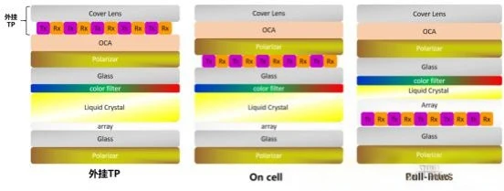
Schematic diagram of 3 mainstream touch control methods
On-cell: The most intuitive understanding is that its touch layers TX and RX are on the upper surface of the TFT-LCD LCD display panel, that is, between the upper surface of the CF glass and the lower surface of the upper polarizer. It is a type of embedded touch technology. On-cell's technology peak was from 2012 to 2015, and was gradually replaced by Full-incell. External TP: It is simply understood that its touch layers TX and RX are completely independent of the TFT-LCD LCD display panel and belong to a separate touch module. The G+G, G+F, G+F+F and OGS are commonly used as common structures of external TP. Plug-in TP technology is currently quite common in some subdivided application fields and has gradually faded out in the consumer market. Full-incell: Full-incell: Full-embedded touch technology, also known as integrated touch and display technology. The locations of its touch layers TX and RX are relatively complicated. It is simply understood that it is between CF glass and TFT glass, which is what we call Cell box. Full-incell technology is currently the most mainstream touch solution and is widely used in products in various fields.
02 What kind of TFT-LCD needs to be coated with conductive silver paste? We will arrange and combine the three mainstream touch modes and two mainstream viewing angle display modes mentioned above, and there will be the following 5 combination solutions. Of course, the combined solution must have existed mainstreamly, such as Full-incell's TN product, we probably haven't seen it. The 5 mainstream combination schemes are as follows:
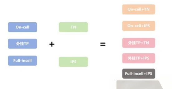
The mainstream combination of TFT-LCD touch mode and display mode is divided into details.
On-cell+TNOn-cell+TN means that Oncell's products adopt the TN viewing angle display mode. The TN product driving method is to control the rotation of the liquid crystal through a vertical electric field to ultimately realize the display of different pictures. Because it is a vertical electric field to conduct conduction, there will definitely be two upper and lower ITO electrodes. The upper ITO electrode (C-ITO) is on the inside of CF and the lower ITO electrode (P-ITO) is on the inside of TFT. The conduction of the upper and lower ITO electrodes is achieved through conductive gold balls doped in the Cell frame glue, which can also improve the anti-static and anti-interference capabilities of the TFT-LCD liquid crystal display panel. Tips: The conductive gold ball doped in the Cell frame glue can not only conduct, but also support CF and TFT glass, ensuring the thickness of the box around the TFT-LCD LCD display panel. Since the conduction and electrostatic release of On-cell+TN products are achieved through the conductive golden ball in the Cell frame glue, there is also an ITO touch layer on the upper surface of the CF of the On-cell panel. After binding the touch FPC, the touch FPC and the display FPC need to be welded together, which can eventually achieve the effect of electrostatic release. Therefore, such products do not need to be coated with conductive silver paste.
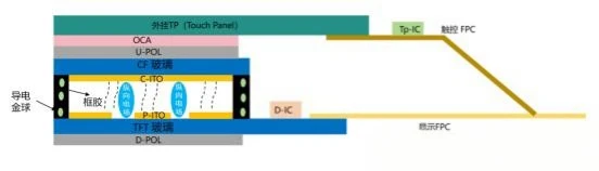
On-cell+TN structure diagram
On-cell+IPSOn-cell+TN, that is, On-cell products adopt IPS viewing angle display mode. The IPS product driving method is to control the rotation of the liquid crystal through a horizontal electric field to ultimately realize the display of different pictures. IPS products also have two electrodes, namely COM electrode (C-ITO) and pixel electrode (P-ITO). Both electrodes are located inside the TFT and are basically on the same plane. After powering on, a horizontal electric field is formed. Therefore, the doped support balls in the Cell frame glue have also been changed to ordinary non-conductive silicon balls. After the TFT-LCD liquid crystal display panel is powered on, the liquid crystal will rotate and realize the display. Since the electrode is on the same plane, the liquid crystal is very susceptible to interference from external noise, so a layer of ITO is required to plate on the upper surface of the CF to shield external interference and conduct static electricity. Since it is an On-cell structure, the existing touch layer on the upper surface of CF acts as an ITO function, which can not only realize touch control but also block external interference. At the same time, after the touch FPC and display FPC are welded together, it can also achieve the effect of electrostatic release. Therefore, such products do not require the coating of conductive silver paste.

On-cell+IPS structure diagram
External TP+TN. External TP+TN. Since its touch layers TX and RX are completely independent of the TFT-LCD LCD display panel, the touch and display work separately and do not affect each other. Judging from the TN product driving method, it is the same as the On-cell+TN mentioned above. There are two upper and lower ITO electrodes on the TFT LCD display panel. The upper ITO electrode (C-ITO) is on the inside of the CF and the lower ITO electrode (P-ITO) is on the inside of the TFT. The conduction of the upper and lower ITO electrodes is achieved through conductive gold doped in the Cell frame glue. This can also improve the anti-static and anti-interference capabilities of the TFT-LCD display panel. Therefore, such products do not require the coating of conductive silver paste.

Schematic diagram of external TP+TN structure
4. External TP+IPS External TP+IPS Compared with external TP+TN, the touch mode is the same, and there will be differences in the viewing angle display mode.
TN's product is a vertical electric field, and the upper and lower ITO electrodes are energized through conductive gold balls in the Cell frame sealing glue. IPS is a horizontal electric field, and the doped support ball in the Cell frame glue has also been changed to an ordinary silicon ball. When the product is powered on, the liquid crystal will rotate and realize the display process. Since the electrode is on the same plane, the liquid crystal is very susceptible to interference from external noise, so a layer of ITO is needed to plate on the upper surface of the CF to shield external interference and conduct static electricity. The ITO film layer plated on the CF surface and the ITO electrode on the TFT are connected by coating conductive silver paste, thereby shielding interference and conducting static electricity. Therefore, such products need to coat conductive silver paste (dot-shaped) at the silver paste dot (AG Pad) of the TFT-LCD liquid crystal display panel, and dot-shaped silver paste dots are coated at the AG Pad on the TFT, and also overlap to the upper surface of the CF. Another point to note is that the ITO film layer is plated on the CF upper surface of the TFT-LCD LCD display panel. After the coating is completed, the ITO impedance must be controlled. It is generally recommended that the ITO impedance is ≤200Ω/□, and the maximum cannot exceed 1000Ω/□.

Schematic diagram of external TP+IPS structure
5. Full-incell+IPS The combination of Full-incell+IPS is currently the most mainstream combination solution and is also the most technically complex. After all, all the modules that implement display and touch are embedded in the Cell box, and the display and touch will interfere with each other.
In order to solve the interference of touch signals and to utilize static conduction, an ATO film needs to be plated on the surface of CF, which is also called a high-resistance film in the industry. The impedance range of the high-resistance film is generally recommended to be 1X10 ^8~9.9X10 ^9Ω/□ (ohms/cube). The ATO film layer plated on the CF surface and the ITO electrode on the TFT are connected by coating conductive silver paste, thereby shielding interference and conducting static electricity. Therefore, such products need to coat conductive silver paste (dot-shaped) at the silver paste dot (AG Pad) of the TFT-LCD liquid crystal display panel, and dot-shaped silver paste dots are coated at the AG Pad on the TFT, and also overlap to the upper surface of the CF.

Full- incell+IPS structural diagram The ATO film is plated on the CF surface. From a technical perspective, it is definitely the best solution, but the ATO film plating will lead to an increase in cost. In order to reduce costs, the current Full-incell+IPS products are all achieved by "canceling the ATO film + low-impedance upper polarizer + coating linear conductive silver paste". During the coating process of linear conductive silver paste, it is necessary to ensure that it is in contact with the sides (thickness direction) of the polarizer on the low impedance to ensure the effect of electrostatic conduction.

Schematic diagram of dot-shaped silver paste and linear silver paste
03 Summary: When doing technology, you must have a sense of awe of technology. Any "should, possible, probable, and perhaps" may plant the root of disaster and ultimately cause unpredictable losses. Therefore, when it comes to technical issues, we must take the attitude of "both wanted and want", and we must know the truth and why, so that we can accumulate and accumulate on the road of technology. There is a lot of talk above. We use a picture to summarize the situation of various combinations of coated conductive silver paste, so as to facilitate better absorption and understanding.

Summary of the coating of each combination of conductive silver paste


