

Hey folks, if you're knee-deep in display engineering-like building monitors, laptops, automotive screens, or industrial panels-you've probably felt the pain of scaling high-resolution LCDs to 4K 240Hz, 8K 120Hz, or beyond. It's not just about more pixels; the real fight is keeping signal integrity rock-solid while battling EMI noise and super-tight timing margins. In 2025-2026 designs, these issues can make or break a product-think flickering, ghosting, failed EMC tests, or just plain bad image quality.
We're talking TFT array layouts on glass getting denser, driver ICs pumping insane data rates, and PCB traces that act like antennas if you're not careful. Let's break it down step by step, pulling from real engineering headaches I've seen (and researched) in recent panels.
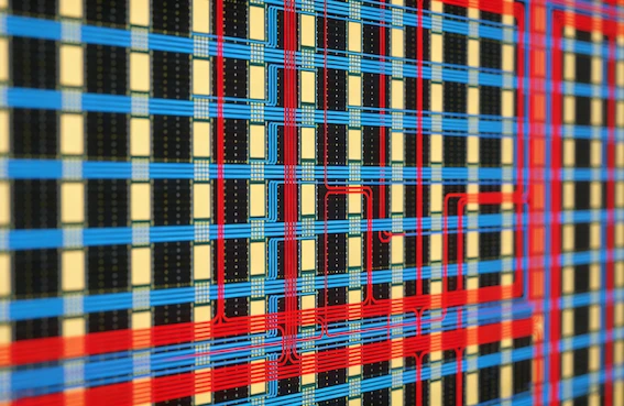
The Core Problem: Explosion in Gate and Source Lines
Jumping to ultra-high resolutions means way more gate lines and source lines crammed onto the glass. A typical 4K panel might have over 8000 gate lines and thousands of source channels-each needing fast, clean switching.
At high refresh rates, pixel charging time shrinks fast. The formula is brutal: Pixel clock (DCLK) = horizontal total pixels × vertical total lines × refresh rate (plus blanking). For 4K at 144Hz, you're easily hitting 500-800 MHz clocks. If RC delays from long traces eat into that tiny window, pixels don't fully charge → colors look washed out, motion blur worsens, or you get flicker in dark scenes.
Engineers fight this with boosted gate voltages or faster LC materials, but that ramps up power, heat, and reliability risks-especially in wide-temp apps like automotive or medical LCDs.
Gate Driver Choices: GIP vs. COF – Trade-offs in High-Res Designs
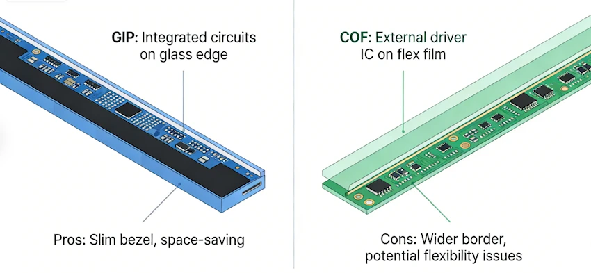
One big decision is how to drive those gate lines: Gate Driver In Panel (GIP) or external Chip on Film (COF).
GIP integrates shift registers right on the glass using a-Si, LTPS, or IGZO TFTs. Pros? Slimmer bezels, lower cost, no extra flex cables-perfect for modern laptops and phones. But in ultra-high-res panels, GIP struggles with Vth shifts under high-frequency stress (more gate pulses = more degradation). Oxide TFTs (IGZO) are great for low power but prone to negative drift; LTPS gives higher mobility for speed but costs more.
To fix charging issues, designs add compensation circuits or multi-line scanning-sometimes cutting effective lines by 20-50% to buy time. Recent oxide-TFT 8K panels use GIP but need careful stress compensation.
COF, on the other hand, mounts driver chips on flex film-easier for high-speed, but it eats border space and adds assembly steps. For super-high refresh, COF often wins on reliability, though GIP is catching up fast in 2025-2026 flagships.
Source Driver Interfaces: LVDS, eDP, MIPI D-PHY – Bandwidth vs. Noise
Source drivers feed pixel data at crazy speeds. Interfaces like LVDS (classic, reliable), eDP (embedded clock, fewer pins-great for laptops), and MIPI D-PHY (low-power, mobile-friendly) all handle 10-20+ Gbps for 8K.
But long traces kill signal quality. Eye diagrams close from attenuation, jitter, crosstalk, and reflections if impedance isn't nailed (100Ω differential ±10%). MIPI shines in mobiles but needs perfect routing to avoid EMI; eDP is picky about pre-emphasis/equalization for longer paths.
Poor eyes = bit errors, screen noise, or sync drops. High-refresh amps this-more data bursts mean more opportunities for glitches.
PCB Layout Mastery: Impedance Control, Ground Planes, and EMI Suppression
This is where battles are won on the driver board. For high-resolution LCD PCBs:
- Impedance control is non-negotiable-differential pairs at 100Ω, single-ended 50Ω. Use 4-6 layer stacks with solid ground planes (no splits under fast traces!).
- Length match data lanes tightly (mils matter at GHz clocks-skew wrecks timing).
- EMI killers: Continuous reference planes for return paths, spread spectrum clocking (SSC) to spread peaks, ferrite beads on power, PI filters, and guard traces.
- Avoid routing over ground cuts-creates antennas. Place vias smartly for stitching.
Ground bounce from switching currents can spike EMI from 200MHz-1GHz. Good decoupling close to ICs and short leads help a ton.
Timing Margin: The Silent Killer in High-Refresh Panels
Everything ties back to timing margin-setup/hold windows for pixel data. Pixel clock drives it all; any propagation delay from TFT RC, driver IC, or traces eats margin.
In high-refresh, windows shrink to nanoseconds. Fixes include faster materials, optimized porch/blanking (reduce total pixels slightly to lower clock), or dynamic schemes.
Automotive/medical add temp extremes-LC viscosity changes shift response, tightening margins further.
Looking Ahead: Future Fixes and Trends
We're seeing more integrated Gate on Array upgrades, hybrid TFTs (LTPO-style for variable refresh), and glass-embedded drivers to slash external parts. But today, success means obsessive simulation (eye diagrams, SI/PI tools), early prototyping, and balancing cost/yield.
Nail TFT array routing, driver IC choices, impedance, and noise control early-or face redesign hell.
If you're tackling a custom LCD project-high-res industrial monitor, car display, medical panel, or next-gen high-refresh setup-our team at Minghua has you covered. We specialize in custom LCD solutions, from TFT array optimization and driver integration to full module builds, with deep know-how in signal integrity for demanding specs. Reach out if you need reliable custom LCD panels that just work. Let's make your next display shine!


